|
Research
|
|
I am working or have worked (i.e.
have general or specific research interests) in the following areas: · Solid
mechanics (computation and theory) in general · Materials
science and in particular studying structure-property relationships · Defect
and micromechanics of materials (e.g. the eigenstrain
fields of inclusions) · Finite-element
modeling · Superplasticity of materials · Dislocation
Dynamics (DD) simulations · Stresses
in thin films (coherent and/or non-coherent interfaces) and critical thickness
evaluation · Fracture
mechanics · Biomechanics
in general · Experimental
mechanics and materials science · Computational
fluid mechanics and in particular in relation to modelling biological fluids
like blood flow. Note:
opportunities for graduate work with Prof. Khraishi
can be learned about by contacting him directly. The
contact info are provided on the homepage of Prof. Khraishi. |
|
The following are examples of the above
performed works: |
|
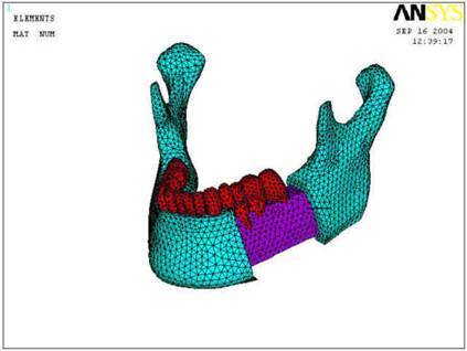
A three-dimensional finite-element
mesh of a human mandible (jaw) showing the hard cortical bone with the soft
cancellous bone behind it. Also shown are the teeth. The jaw is subject to
realistic boundary conditions encountered when biting. This CAD can be used
to model mandibular fractures fixated with a plate-screw system as shown
below. |
|
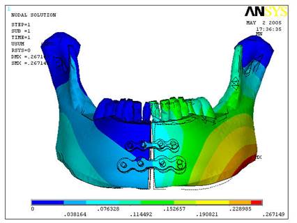
The above picture shows a symphyseal mandibular fracture (fracture along the
symmetry plane of the jaw) fixated with two band plates of different sizes
each having four screws inserted through the plate and bone. |
|
The above is a movie showing the fixated mandibular fracture, fixated
using a ladder plate, during mastication (i.e. biting). |
|
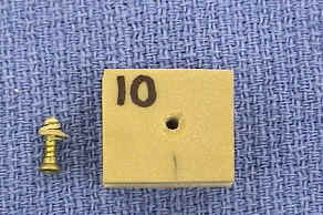
A picture showing screw (in
particular a screw used in mandibular fracture fixation) pull-out
from synthetic bone mimicking mandibular bone. The pullout resulted in this
case in bone entrapped between the screw teeth like a cone. |
|
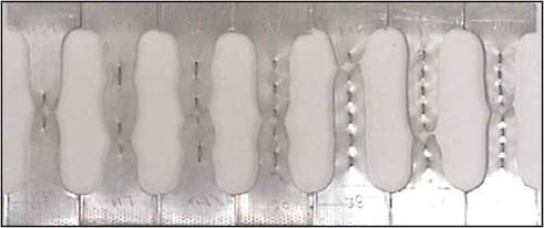
Seven dog bone-shaped
experimental tensile specimens with one to seven holes in their gauge length.
The material is superplastic. This picture shows the unintuitive result that,
with proper selection of the applied |
|
A dog bone-shaped specimen with three holes in its gauge length subjected to tension under a constant strain rate. The circular holes run through the thickness. |
|
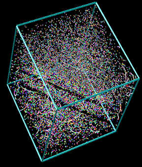
Here shown is the 3-D
interaction of particles (here spherical with a volume misfit or normal eigenstrains) with gliding dislocations, on a single slip
plane, to predict the strengthening effect of such particles. Dynamic
Pile-ups of glide dislocation loops form in the glide plane above the
particles. This is different than the conventional Orowan-loop mechanism whereby a relatively strong
particle is surrounded by a pile-up of dislocation loops. The above can be captured using the three-dimensional discrete
dislocation dynamics (DD) methodology. |
|
The 3D interaction of a gliding dislocation with Helium bubbles (pressurized nano voids) in irradiated metals to predict the mechanical hardening effect of the bubbles. |
|
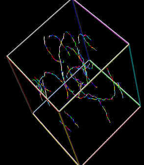
A 3-D picture of a dislocation dynamics (DD) computational cell illustrating the formation of channels free of irradiation damage clusters (left). The tiny dots in the figure represent such defect clusters. The underlying dislocation structure (not clear on the left), which is responsible for the clear channels, is shown to the right. |
|
A DD simulation of the operation of a single Frank-Read dislocation source gliding on a crystallographic slip plane. |
|
The initial (solid circles) and final (circles with markers) locations/configurations of two glide dislocation loops surrounding a rigid cylindrical fiber and contracting under their own line tension effect. The initial loops radii are 1200b and 2000b and the final loops radii are 891b and 1764b. The fiber length and radius are 400b and 500b, respectively. b is the magnitude of a Burgers vector. |
|
A snapshot of the interaction between a gliding dislocation and an immobile dislocation tilt wall, i.e. a low-angle grain boundary, of the same sign as this dislocation. A dynamic and linear glide dislocation pile-up has formed in front of the wall. Here, the gliding dislocation is on a direct collision course with one of the tilt wall dislocations. |
|
A simulation of the interaction of a pinned dislocation source with a free surface close to it. Notice how the surface sucks in the dislocation to reduce the elastic energy in the crystal. |
|
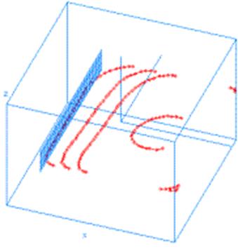
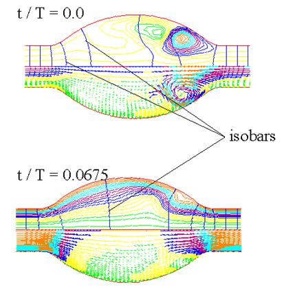
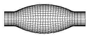
Streamline Contour and Pressure Contour (isobar) plots along with Velocity Vector plots for transient or unsteady blood flow in a symmetric abdominal aortic aneurysm (AAA). The top one is shown at the end of diastole and the lower one is shown during systole. Also shown to the right is the finite-element mesh used in the simulation. |
|
Streamline, vector and pressure contour plots (from top to bottom) for a AAA Model with renal and iliac branches at Re (Reynolds Number) = 333. Flow inlets at left as a steady parabolic flow. |
|
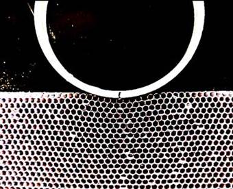
Left: An
array of straws, 1 inch long each, mimicking a FCC (111) close-packed plane
of atoms undergoing elastic deformation when subjected to indentation by a
circular indenter. The indenter pushes into the atomic plane, but up to this moment no defects have nucleated. |
|
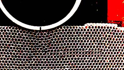
Interstitials have a strong effect on triggering plasticity in a crystal. Here, a whole triangle, containing an interstitial, slips although the interstitial is far away from the indenter. |
|
Using linear elastic fracture mechanics, the shapes of the crack tip plastic zone under Plane Stress conditions, Mode II fracture opening/loading, and using the Von Mises (solid line) and Tresca yield criteria are shown. The crack runs from negative x till zero (i.e. the tip is at x = 0). |
|
The crack tip plastic zone for Mode I Plane Strain using the Von Mises Criterion for different Poisson’s Ratios (From outer to inner n = 0.1,0.2,0.3,0.4). |
|
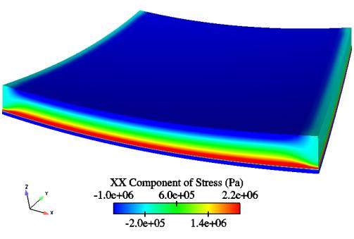
A 3-D XFEM (the eXtended Finite-Element Method) simulation showing developed curvature in a thin film-substrate heteroepitaxial bi-layer structure. |
|
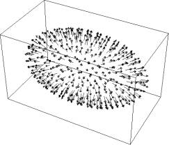
A
volume-misfit ellipsoidal particle with normal eigenstrains.
A computational approach to calculate the elastic fields (i.e. displacements,
strains and stresses) of a particle of any shape and misfit geometry is
developed based on discretizing the surface misfit region into smaller
finite-sized regions each of which is represented by a dislocation loop with
an appropriate choice of its Burgers vector (see the vectors in the figure).
Here, the particle surface is comprised of 408 elements/dislocation loops. Also here, the lengths of the semi-axes are 200b,
100b, and 100b along the x, y and z-directions,
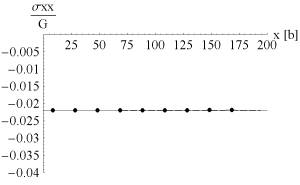
respectively. To the right is shown how calculations
from this method (dots) match theory (solid line) for stress magnitude and
distribution inside the particle. |