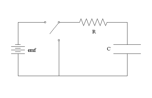
When the toggle switch is in the open position shown in the diagram, the capacitor is not connected the Electromotive Force, emf, and, unless the capacitor was previously charged, there will be no charges stored in the capacitor (i.e., q = 0) and the potential difference between the plates of the capacitor will correspondingly be zero as well.
If the switch is toggled so that it connects the capacitor to the Electromotive Force, charges will tend to accumulate on the plates of the capacitor, + on one plate, _ on the other. This will continue until the accumulated charge creates a potential difference (Vc) between the two plates that is numerically equal to the electromotive force. That is, when:
current flow through the connecting wires will cease (i.e., I = 0).
When the switch is toggled to its alternate position, (i) the emf is bypassed, (ii) the two plates of the capacitor are connected, and (iii) the charges stored on the capacitor will tend to pass through the connecting wire to the opposite plate. In other words, the charged capacitor will discharge.
There are 2 important things to remember about the electrical properties of R-C circuits:
1. When the capacitor (C) is fully charged, the following relationship holds:
q = Ce Equation 1a where q is the total amount of charge stored by the capacitor, C is the capacitance of the capacitor, and e is the electromotive force that is actually charging the capacitor. Note that q = 0 when the capacitor is discharged. Also note that the equation may be rearranged thus:
q/C = e = Vc Equation 1b meaning that placing excess + on one plate of the capacitor and excess – on the other plate will generate a potential difference between the plates.
2. Because of the presence of a resistance (R) in the circuit, current flow through the circuit is slowed. As a result, changing the amount of charge stored on the plates of the capacitor requires time. For example, if you were to start with a completely discharged capacitor (i.e., q = 0 and Vc = 0) and connect it to a battery, the charging of the capacitor would be described by an exponential equation,
qt = Ce(1 – e-t/RC) Equation 2a and if C = 1, e = 10, and R = 1, the graph of qt vs. time would look like this:
Similarly, if you were to start with the same capacitor in the fully charged state (i.e., q = Ce and Vc = e ) and connect its two plates to each other, the discharging of the capacitor would be described by an exponential equation:
qt = Ce e-t/RC Equation 2b and the graph of qt vs. time would look like this:
Exercises:
1. Keeping in mind Equations 1b, 2a, and 2b, and the definition of current, can you predict the appearance of the graphs of Vc and current (I) vs. time for the same R-C circuit?
2. Run the simulations of R-C Circuit Electrical Properties, and get a qualitative feel for the effect of varying e on the electrical ‘behavior’ of an R-C circuit.
3. The quantity RC is termed the time constant of the R-C circuit, and is sometimes represented as t (= RC). Investigate the effects of varying t on the electrical 'behavior' of an R-C circuit by repeating Exercise 2, this time varying R and/or C. Can you think of any way(s) in which the results of this exercise might be relevant to an excitable cell’s plasma membrane (hint: recall the Equivalent Circuit Model)?

